
In our previous post, we explored how TCP Multipath and OneFS SmartConnect can enhance PowerScale performance. Today, we shift our focus to the power of Remote Direct Memory Access (RDMA) and how to configure it in your network for low-latency, high-throughput data transfers. We will cover some suggested steps in configuring a switch, server, and PowerScale nodes, along with essential verification commands to ensure everything is working optimally.
As someone who spent part of their career as a network engineer, I wanted to shed some light on the end-to-end RDMA process rather than just focusing on the PowerScale side of the equation. Having worked with RDMA (on and off) over the years, I’ve always found it useful (and necessary) to see the complete flow of an end-to-end RDMA topology — information that can be hard to come by! Plus, I get to nerd out a bit in this post. 🙂
The topology used in this blog for RDMA is simple, as we are utilizing a single switch for both the server and PowerScale nodes. All NICs are active (no leaf-spine architecture, no LAG, no LACP on the PowerScale nodes). However, it still serves as a good foundation of the fundamentals. It also varies from “traditional” RDMA implementations because we are using the multipath client driver to handle RDMA traffic on the server side rather than relying on “traditional” Linux modules. There’s some good documentation and videos out there covering standard, non-multipath approaches, which I recommend checking out.
Should we configure LACP on the PowerScale nodes?
Well, this is a matter of debate! LACP can distribute traffic across the NICs on individual PowerScale nodes, which could potentially increase throughput for multiple network streams. However, it’s important to note that LACP aggregates traffic at the session level, not the packet level. So, while it can enhance throughput for multiple streams, it won’t double the bandwidth for a single data flow. Since we’re focusing on RDMA and the multipath driver to increase throughput to multiple NICs on multiple nodes, I opted not to enable LACP in this lab setup. That said, I may explore LACP in future tests to compare performance.
As we know, RDMA can drastically reduce CPU load and improve bandwidth utilization, making it ideal for high-performance workloads. Let’s dive into the details of configuring an end-to-end RDMA setup for PowerScale.
Test Rig RDMA setup
For these tests, we built an end-to-end 100GbE test scenario with high-performance hardware:
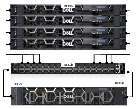
- PowerScale Array: 4x PowerScale F210 nodes
- Switch: 100GbE switch connecting the PowerScale nodes to the test server (Z9100-ON Series)
- Test Server: Dell PowerEdge R7525, 128 Core/256 Threads AMD ThreadRipper CPU, outfitted with dual 100GbE NICs, running Red Hat Enterprise Linux 8 (RHEL8).
we’re going to focus on configuring RDMA for a simple lab setup using RoCEv2 (RDMA over Converged Ethernet). For this setup, we will be relying on Link-Level Flow Control (LLFC), as it is the supported option for ensuring lossless behavior in our environment.
Ill be expanding on the following useful resource by Nick Trimbee – NFS over RDMA Cluster Configuration.
So what do we need to do ?
There will be several step that we need to follow – but the configuration is relatively straight forward ! the flow will be as follows.
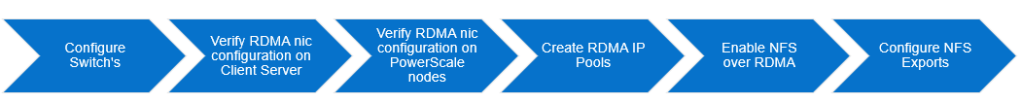
Config examples will only be for one interface for illustrative purposes (The test setup uses two)
Step -1 – Z9100 Switch
We’ll start with the switch configuration, Why LLFC for Our Setup? LLFC is simpler to implement in a lab setup and provides lossless transmission for RDMA traffic across all interfaces without needing to configure specific priority classes. This makes it ideal for smaller, dedicated RoCEv2 networks where performance concerns around non-RDMA traffic are minimal.
Switch Configuration Using LLFC
To ensure that our network operates with lossless behavior across all interfaces, Link-Level Flow Control will be enabled on the switch. Below is the configuration example for Dell Z9100 switches:
- Enable LLFC on Interfaces: We enable flow control on both receive (
rx) and transmit (tx) directions for the interfaces handling RDMA traffic.
interface hundredGigE 1/13
flowcontrol rx on tx on
mtu 9416
no shutdown
The MTU is set to 9416 to support jumbo frames, which allows for efficient transmission of large packets, reducing fragmentation and improving throughput.
How LLFC Works for RoCEv2 in This Setup
In this configuration, LLFC will ensure that all traffic on the interface (including RDMA) is lossless. If network congestion occurs, the switch will pause all traffic, ensuring that no packets are dropped, including RDMA packets.
Why We Chose LLFC Over PFC for This Lab
- Simplicity: LLFC is easier to configure and is fully supported in our current lab environment. For a small, dedicated network focused solely on RDMA traffic, this provides a simple solution without the need to manage multiple priority classes.
- Future Considerations: While PFC provides more fine-grained control, it requires additional configuration (e.g., Data Center Bridging and priority class management). In future setups, where both RDMA and non-RDMA traffic are mixed, PFC would be a more appropriate choice to avoid head-of-line blocking and to allow normal Ethernet traffic to pass unaffected. (and beyond the scope of this blog post!)
In the next section, we’ll cover verifying RDMA functionality on your Linux server to ensure that everything is properly configured.
Step 2 – Configuring and verifying your server
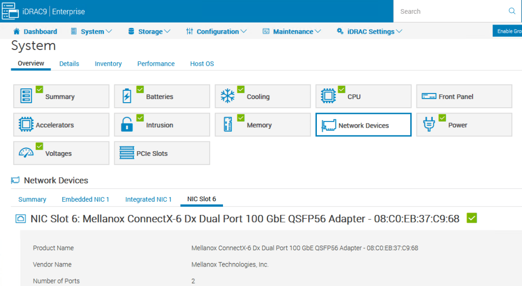
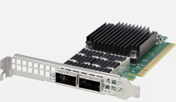
Firstly we need to use use nics that are RDMA certified – in our test set we are using a Mellanox ConnectX-6 Dual Port 100Gb nic – we know this supports RDMA and hardware offload.
On Red Hat (or similar Linux distributions), the RDMA service (rdma-core package) will manage RDMA devices and services in the background.
Since our NICs are capable of RDMA, this service automatically takes care of device initialization when they are detected. Lets quickly verify this
[root@hop-r7525-01 ~]# rpm -qa | grep rdma
kmod-mlnx-nfsrdma-5.9-OFED.5.9.0.5.4.1.202310081454.rhel9u2.x86_64
librdmacm-59mlnx44-1.59056.x86_64
rdma-core-devel-59mlnx44-1.59056.x86_64
ucx-rdmacm-1.15.0-1.59056.x86_64
librdmacm-utils-59mlnx44-1.59056.x86_64
rdma-core-59mlnx44-1.59056.x86_64
We have the rdma core package installed (good) – running the command ibv_devices we can see these RDMA capable nics on our host
[root@RHEL9]# ibv_devices
device node GUID
------ ----------------
mlx5_0 08c0eb030037c968
mlx5_1 08c0eb030037c969
Lets verify they have negotiated to use RoCEv2 on the nics – Link Layer: Ethernet confirms it’s RoCEv2, and not InfiniBand.
[root@RHEL9]# ibv_devinfo -d mlx5_0
hca_id: mlx5_0
transport: InfiniBand (0)
link_layer: Ethernet
Lastly, let verify the RDMA links are up on the nics
# rdma link show
link mlx5_0/1 state ACTIVE physical_state LINK_UP netdev ens6f0np0
link mlx5_1/1 state ACTIVE physical_state LINK_UP netdev ens6f1np1
Output looks good! The RDMA links mlx5_0 (associated with ens6f0np0) and mlx5_1 (associated with ens6f1np1) are both in the ACTIVE state, with their physical state showing LINK_UP. This means that both RDMA interfaces are functioning correctly and are ready for traffic.
Key points from your output:
- state ACTIVE: Indicates that the RDMA link is up and active, which is what you want for RDMA communication.
- physical_state LINK_UP: Confirms that the physical network connection is established and operational.
We’re all set from an RDMA configuration perspective! Both NICs are properly configured and ready for high-performance, low-latency RDMA transfers. Well to the switch at lest ! last lets switch over to the PowerScale Cluster to complete the picture
RDMA Configuration: Simplicity by Design
One important aspect of this setup is the minimal manual configuration required to get RDMA working. After installing RHEL, the RDMA modules (such as rdma-core) were already present and managed by the system. The only manual step was installing the Mellanox ConnectX-6 drivers, and after that, the system automatically handled the RDMA device initialization and configuration.
Thanks to the support baked into the RHEL distribution and the capabilities of the ConnectX NICs, everything else was auto-negotiated. This included:
- Enabling RDMA: The
rdma-corepackage manages the RDMA stack, which comes pre-installed on RHEL. - RoCEv2 Configuration: The network interface automatically negotiated to use RoCEv2 based on the Ethernet environment and switch settings.
- Link-Level Flow Control: LLFC on the switch ensured lossless transmission without needing additional configuration on the host side.
In short, after installing the necessary drivers, RDMA just worked—making it easier to focus on testing and performance rather than complex configuration.
It’s important to note that even though we’ve configured RDMA (RoCEv2), the Mellanox ConnectX NIC will continue to function as a standard Ethernet NIC for all regular network operations. It supports both RDMA and TCP/IP (This will be important of our “real world” testing in our next blog)
- RDMA: For high-performance, low-latency communication over RoCEv2.
- Standard TCP/IP: For all normal network traffic like file transfers, web access, and other TCP-based communications.
The NIC dynamically switches between these modes depending on the application. If an application requests RDMA, the NIC uses RoCEv2. Otherwise, it behaves like a normal NIC, handling typical network traffic with TCP/IP. This flexibility allows the NIC to operate seamlessly in both high-performance and standard environments.
As this blog is part of a series we will not be using the standard Linux RDMA module to handle or traffic, we’ll instead be using the client multipath Driver as covered here
Step 3 – Configuring and verifying the PowerScale Cluster
Nick Trimbee has outlined this process in detail here however for the sake of completeness lets verify our cluster
First, from the OneFS CLI, verify which of the cluster’s front-end network interfaces support the ROCEv2 capability. This can be determined by running the following CLI command to find the interfaces that report ‘SUPPORTS_RDMA_RRoCE’.
f210-1# isi network interfaces list -v
        IP Addresses: 192.168.1.201
                 LNN: 1
                Name: 100gige-1
            NIC Name: mce3
              Owners: groupnet0.subnet0.pool0
              Status: Up
             VLAN ID: -
Default IPv4 Gateway: 192.168.1.1
Default IPv6 Gateway: -
                 MTU: 9000
         Access Zone: System
               Flags: SUPPORTS_RDMA_RRoCE
    Negotiated Speed: 100Gbps
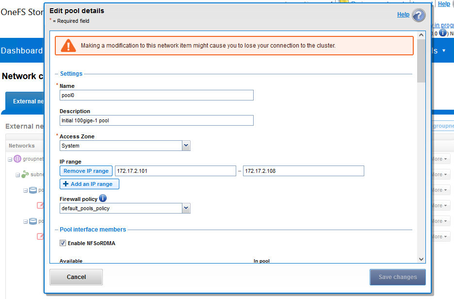
Navigating to Cluster management > Network configuration can create or edit an IP pool that contains the ROCEv2 capable network interface(s). Here I have enabled NFSoRDMA for my 100Gb IP Pool for the PowerScale Cluster.
Next, under Protocols > UNIX sharing (NFS) > Global settings and enable the cluster NFS service, the NFSoRDMA functionality, and the desired protocols versions
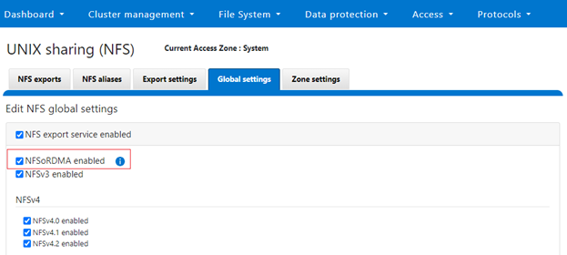
Note that OneFS checks to ensure that the cluster’s NICs are RDMA-capable before allowing the NFSoRDMA setting to be enabled.
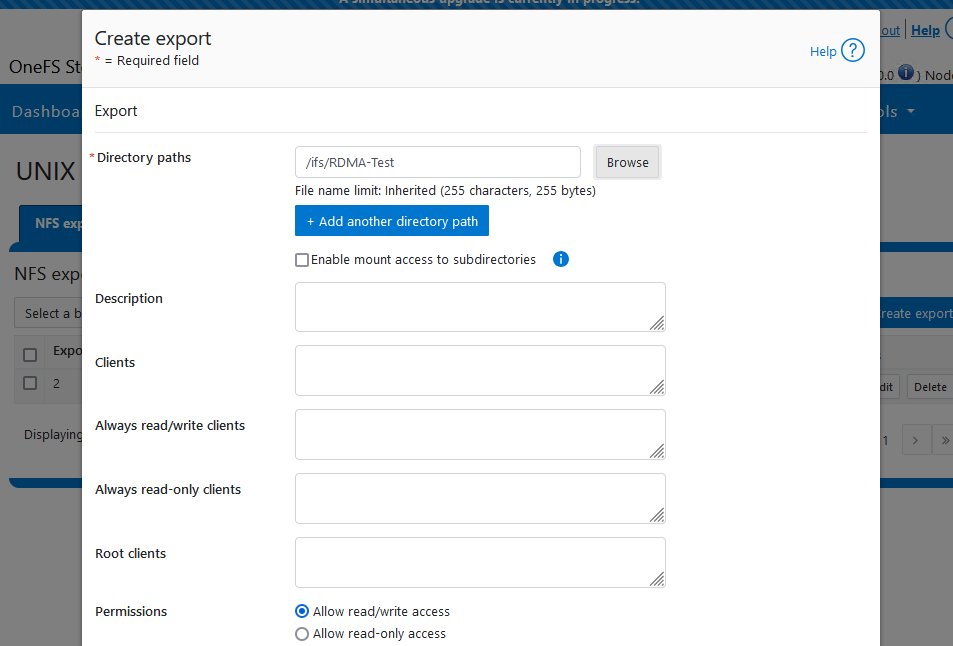
Finally, Create and export for testing – In our case I have created a directory called RDMA-Test (firstly) and exported it as shown.
Note this is a standard export (like any other) the difference here is that we will mount it using the RDMA protocol in the next step
Step 5 – Connecting to share via NFSoRDMA
Mounting NFS over RDMA with Multipath Client Driver
In my previous blog, we explored how TCP Multipath and OneFS SmartConnect can boost PowerScale performance by allowing clients to access multiple nodes simultaneously. This time, we take it a step further by using the multipath client driver to mount NFS over RDMA, optimizing both throughput and connection reliability for high-performance workloads.
Here’s the command I’m using to mount the NFS share over RDMA:
[root@7525-01 ~]# mkdir -p /home/damian/RDMA-Test

[root@7525-01 ~]# mount 192.168.1.201:/ifs/data/f210/perforce/nfs_mp_rdma_depot /mnt/rdma-multipath \
nfs proto=rdma,port=20049,vers=4.1,nconnect=32,localports=192.168.1.21-192.168.1.22,remoteports=192.168.1.201-192.168.1.204,\
rsize=1048576,wsize=1048576,timeo=10,soft 0 0
This command specifies several key options:
- proto=rdma: This tells the client to use RDMA for data transfers, bypassing standard TCP/IP for faster, low-latency communication.
- nconnect=32: We are using multiple connections to improve parallelism and throughput by taking full advantage of RDMA’s low-latency capabilities.
- localports and remoteports: By specifying local (i.e. ip address of the servers two 100Gb nics) and remote port ranges (the ip addresses of each node), we ensure efficient and balanced distribution of traffic across multiple paths and network interfaces.
Let’s Verify
On our Ubuntu client, we can see that the share is successfully mounted using the multipath driver (I used the df -h command to verify). Here, you can see we have our RDMA mount using the Multipath client driver—pretty cool!
[root@sea-p4-01 ~]# df -h
Filesystem                                               Size  Used Avail Use% Mounted on

192.168.1.201:/ifs/data/f210/perforce/nfs_mp_rdma_depot  222T  170T   23T  89% /mnt/rdma-multipath
tmpfs                                                     26G     0   26G   0% /run/user/0
Over on the PowerScale cluster running the command isi_for_array 'isi_nfs4mgmt'will list out the connection type on each of the PowerScale Nodes in the cluster – formatting is a little clunky in this blog however we have a connection over RDMA to each node in our cluster from the server i.e. 1 -> 4 (Pretty cool!)
f210-1# isi_for_array 'isi_nfs4mgmt'
f210-1: ID Vers Conn SessionId Client Address Port O-Owners Opens Handles L-Owners
f210-1: 7216841077559855942 4.1 rdma 3 192.168.1.21 35222 0 0 0 0
f210-3: ID Vers Conn SessionId Client Address Port O-Owners Opens Handles L-Owners
f210-3: 4541013222386432161 4.1 rdma 1 192.168.1.21 49943 0 0 0 0
f210-4: ID Vers Conn SessionId Client Address Port O-Owners Opens Handles L-Owners
f210-4: 7854004635227843600 4.1 rdma 1 192.168.1.21 43257 0 0 0 0
f210-2: ID Vers Conn SessionId Client Address Port O-Owners Opens Handles L-Owners
f210-2: 6059076826531286528 4.1 rdma 1 192.168.1.21 45662 0 0 0 0
Lets throw some I/O at the cluster – I’m using fio as a simple test to read and write sequentially to a file on the NFS Share /mnt/rdma-multipath
using the command isi statistics system -n=all --format top we can see we writing to all nodes in the cluster (again, pretty cool!)
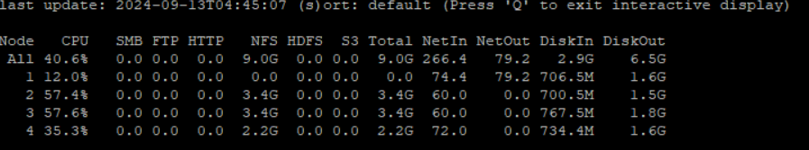
Stay tuned for our next blog, where we’ll be hosting a bake-off to compare performance across these configurations i.e. TCP. TCP MultiPath, RDMA, RDMA Multipath.

Leave a comment